Add 2 travel switches KM to the double interlocking forward and reverse control circuit (as shown in the red line part of the circuit in Figure 1), and the travel switch can automatically control the forward and reverse rotation of the motor.
In the circuit diagram, KM1 is a forward (forward) travel switch, KM2 is a retrograde (reverse) travel switch, and KM1 and KM2 form an interlock travel switch. The function is the same as the forward and reverse start button. The overall circuit is a triple interlocking control circuit, which has good electrical safety performance.

Limit switches, also known as travel switches, can be installed on relatively stationary objects (such as fixed frames, door frames, etc., referred to as still life) or moving objects (such as vehicles, doors, etc., referred to as animals). When the animal approaches the still life, the link of the switch drives the contacts of the switch to cause the closed contacts to open or the open contacts to close. By the change of the open and closed state of the switch contact, the control circuit and the motor can be signaled.
The circuit diagram of the forward and reverse rotation of the limit switch control slip motor is as follows

Extended information:
Limit switch classification
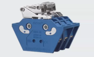
The limit switch is mainly composed of switch elements, wiring terminals, switch actuators, and transmission parts. According to the mechanical mechanism of the switch contact on and off, the switch elements are classified into two categories.
1. Slow switch
The switching time of the on and off actions of the switch is related to the operating frequency of the switch. The faster the operating frequency, the faster the switching of the switch.
2. Speed and large switch
The switching time of the switch on and off has nothing to do with the frequency of the switch being operated. As long as the switch is operated to a certain position, the switch will switch on and off. This process time is generally the time required for the spring to bounce. This time period is a constant.
Web: www.cnswitch.cn
Tel/Fax: 0086-577-62840011
Wechat/WhatsApp: 008613355775769
Zhejiang SHUYI Electric Co., LTD, Focus on switches with 30 years.
An original factory of micro switch; foot switch; toggle switch; limit switch from China.
#limitswitch#chinashuyi#rollerlimitswitch #rollerpiungertypelimitswitch
#ZJSHUYI #cnswitch#tyerlimitswitch #safetylimitswitch #sealedlimitswitch